Posted: Thu Feb 12, 2009 15:48 Post subject: WRT54G V5 Flash Memory Upgrade Success!
Alrite I decided that because the mods to the WRT54GV5 were a bit off topic in the previous thread; I decided to create a new topic dedicated to modding the WRT54G V5.
Okay so just a recap - the idea was to enable the WRT54G V5 to handle up to 32Mb [4Megabytes] of flash memory so that the user can run DD-WRT Standard Edition. [The assumption being that because both Broadcom chipsets on the V4 and V5 routers are the same; it should in theory mean that the V5 is capable of addressing and supporting 4MB of flash memory] Now for those who ask;
"Where did you get the standard edition
from; considering that Brainslayer never made a standard edition for the V5 routers".
As I said before; because we know that the chipsets on the V4 and V5 routers are the same; it means that we can use the SAME firmware images [GENERIC] that Brainslayer made for the V4 router on the V5.
Below is a screenshot to demonstrate that the V4 and V5 micro images are EXACTLY the same; suggesting that we can use V4 images on the V5 flawlessly
Now that we have the firmware issue resolved we need to only concern ourselves with two issues, those being;
1) What Flash chip can/do we use?
2) Are all the Address Lines connected to allow for full access to the flash chip??
A1) I am assuming that because the V4 router used the Intel TE28F320 - 4MB flash chip; it means that the V5 can too address similar 4MB TSOP 48 Pin chips. In order to keep any compatibility issues to a bare minimum; I opted to use 4MB flash chips which were already supported in the JTAG Debrick Utility. Check the readme for suitable flash chips.
A2) What we really need is for the A20 address line [Pin 10] to be connected to the Broadcom chipset; in order to utilise the full 4MB of flash memory. After closely investigating the V5 PCB; I came to the realisation that the A20 lane IS in fact connected IF your router has the following resistor connected.
*Hehe mind my little “bridging wires” on the other parts of the PCB….I have desoldered and resoldered different flash chips / memory chips that I had laying around almost 20x over and kinda inadvertently busted a few pads on the board *
If this particular resistor is NOT present for you; your best bet is to de-solder an SMD resistor from another device. If you cannot get your hands on one, you can alternatively opt to bridge the point with a thin piece of copper wire [Not recommended].
Now that we have established and addressed our two possible hardware issues its time to actually do the flash chip swap.
Once you have swapped the flash chip; you should have something like this [Minus the bridging wires unless of course you too have broken the pads on the board ^^”]
Now its basically a matter of erasing the whole flash chip; then loading the CFE.bin into the flash chip; followed by flashing in the Kernel.bin. Just a note you can flash the kernel both ways - either via jtag or by tftp; whichever suits you.
However; in order to perform the flash chip erasure and CFE flash; you are going to need the Debrick Utility + a Jtag cable. I am assuming you have them and know how to use them.
Once you connect them; do a full chip erasure by doing;
wrt54g -erase:wholeflash /noreset
Your chip should be automatically detected, like mine was ;
It is STRONGLY advised that you do a power cycle after each process and use the /noreset switch.
Once you have done that; grab whatever generic firmware you want to load in from the V4 page [EXCLUDING MEGA!].
You can flash it either via JTAG or TFTP.
I wont list the instructions for the TFTP method; but below are the instructions for the JTAG method;
If you were able to successfully follow these steps; you too should have a WRT54G V5 running 4MB of flash memory and running a firmware image other than Micro.
In upcoming weeks I am going to see if the SD card hack can be done on the V5; and also attempt to upgrade the ram on this unit; as the configuration pages tend to lag at times due to the lack of memory.
Stay tuned!
Just a note: THIS HACK IS NOT INTENDED FOR THE FAINT HEARTED NOR THOSE WHO HAVE LITTLE / NO EXPERIENCE WITH SMD SOLDERING!!!! While this hack worked perfectly for me; I cannot guarantee success for you with your equipment used; nor can I be held responsible for any damage you cause to your equipment; or be held responsible for providing inaccurate information - the information is here for "educational purposes". As mbellot astutely pointed out;
"If you choose to follow these directions you accept any and all responsibility for the state of your router when you're done."
Posted: Wed Feb 18, 2009 13:19 Post subject: WRT54G V5 Memory Upgrade
A few days have lapsed since my last post; so I decided to let you guys know how the memory upgrade went.
I got hold of a new SODIMM PC133 memory module from Ebay; which cost me about $4US. For those who are interested in purchasing these cheap; yet good quality and new modules; below is a link;
Before I proceed; I’m going to point out that when you calculate the capacity per chip; it may/may not be the same; as these memory chips are going to function in 16 bit mode when installed.
FYI; below is an example of how it’s done;
Total Width of Memory = 64 [Always 64].
Number of total chips on stick = 8 [Double Sided SODIMM]
Thus; we have 256 / 8 = 32MB of Memory in 8 Bit Mode.
But remember; the router functions in 16 bit mode; so we simply halve the capacity per chip to get the size in 16 bit mode = 32MB / 2 = 16MB.
NOTE: unlike the flash chip upgrade; where you can use the JTAG debrick utility to actually probe the flash chip to see if it is/isn’t present; the ram cannot be probed - so ensure that the router can boot up successfully before modifying anything; otherwise diagnosing the fault will be nearly impossible at the end of this hack.
Now that’s sorted; lets go straight to modding it!
A bit of background information on what the "Maximum" limit is.
The fundamental reason as to why this unit CANNOT support more than 16MB of ram is due to the fact that pin 36 [Address line A12] is not in any way connected to the Broadcom chipset. This means that the CPU cannot "see" more than 16MB of ram; even if you were to purchase and solder in a 32MB Memory chip. This is why I opted to buy the cheaper 16MB memory chips instead. Also; because the SD Memory bus was originally rated at 133mhz on the Broadcom BCM5352 [I may stand to be corrected on this point ]; the chipset will not experience any problems with PC133 SODIMM chips.
**!NOTE!** The WRT54GV5 DOES NOT SUPPORT DDR MEMORY!!!! DO NOT under any circumstances attempt to solder such a chip to the unit; otherwise you WILL convert your WRT54GV5 into an expensive paperweight :P
Now that’s done; what you now need to do is peel off any stickers obstructing the legs of the memory chip; and clean with alcohol if any sticky residue is left behind.
Then carefully de-solder the memory chip from the SODIMM as per the instructions set out in the video in my last post.
Repeat the same procedure on the WRT54G V5 motherboard; while observing the orientation of the existing memory chip. Due to the extreme temperature of the soldering iron; the hot glue used to secure other components very close to the memory chip may start to melt and flow onto the memory chips pads. If this happens; make sure that you wipe the glue off IMMEDIATELY with a cotton bud; then use flux [liquid or paste - it doesn’t matter] to clean the pads to ensure a solid electrical connection. For those who didn’t observe the orientation of the ram chip; below is a picture depicting where pin 1 coincides with the motherboard.
If you somehow pull a pad or two; don’t be too worried...Simply retrace its path. Then use the corner of a sharp scraper blade and gently scrape the green PCB coating off until you uncover the copper layer. Now simply get a very thin wire [I recommend you use the strands from an old IDE cable] and solder it to both the leg of the ram chip and the trace which you uncovered.
Before applying power to the board; visually inspect your soldering job; ensuring that both the contacts of the memory legs to the memory pads are joined properly; and that you didn’t accidentally short / remove any capacitors/resistors along the sides of the ram chip. Below is a picture of how the smd resistors / capacitors should be organised on the board:
If somehow you did remove a capacitor / resistor and can not find it; try to find one similar to the one next to the displaced component. If that isn’t possible; you can short the two contacts with a thin piece of copper wire; although I do not recommend this as you may experience unexpected results during operation.
Now that you have completed the memory swap; it is time to power up the board. If the router appears to be in a bricked state - power off the unit and re-check your soldering job.
IF however the unit boots up normally; you have successfully upgraded the ram on the unit [The hardware part only!].
Now; because the CFE [Common Firmware Environment] on the WRT54G V5 was only ever programmed to detect 8MB of ram; you will only see "8MB" of ram on the Sys-info page.
But not to worry! With a few little commands you can enable the full 16MB of ram on this unit.
CREDITS for the commands GO TO Milkman!
Run Command Prompt and telnet into your router.
Once at the DD-WRT screen; simply type in the following commands:
nvram set sdram_init=0x0A
nvram set sdram_ncdl=0x0000
nvram commit
Reboot the unit in the DD-WRT webpage. After a few seconds go to the sys-info page and you should now see the 16MB.
But if for some reason your NV-Ram got corrupted and you don’t want to go thru the hassle of re-entering in these commands; or you want to install Standard SP1 on your V5 without it locking up every 10 seconds; you will need to recompile the CFE to enable the 16MB by default.
But not to worry. I went to all the effort to recompile the V5 CFE to include the 16MB; so you will never have to enter in the commands ever again. Simply grab your JTAG cable and the debrick utility and erase your existing CFE AND your NV-RAM; then program my CFE into your router and bingo - you will always have 16MB of ram set up by default, which isn’t dependent on the NVRAM partition. Below is the link to my CFE
If you successfully flashed in my CFE; or entered in the commands [Whichever suits your convenience] - you should now have 16MB of ram at your disposal. Below is a picture of my setup using DD-WRT V24 SP1 Standard + 16MB of ram which is enabled thru the CFE:
As I said before; and am re-emphasising again:
Just a note: THIS HACK IS NOT INTENDED FOR THE FAINT HEARTED NOR THOSE WHO HAVE LITTLE / NO EXPERIENCE WITH SMD SOLDERING!!!! While this hack worked perfectly for me; I cannot guarantee success for you with your equipment used; nor can I be held responsible for any damage you cause to your equipment; or be held responsible for providing inaccurate information - the information is here for "educational purposes".
Please feel free to let me know what you think; along with your results.
Posted: Sat Mar 28, 2009 17:47 Post subject: Thanks!
Thanks to your post (and Milkman as well), I've upgraded my WRT54G V5 to 16MB of RAM.
I'm considering performing the flash upgrade as well - I've got the chip, unfortunately, I don't have the correct adapter for my eprom programmer. Either I'll pick up an adapter or try using JTAG (don't have that yet and have never used it or the software).
One question - does the micro version of dd-wrt actually make use of the extra memory (or is it coded in such a way to run with 8MB only?) If so, that makes the memory upgrade pointless without the flash upgrade as well...
Joined: 04 Jan 2007 Posts: 11564 Location: Wherever the wind blows- North America
Posted: Sat Mar 28, 2009 17:55 Post subject:
Personally, I would try using the CFE from the GSv5 model...then the 16M would be recognized by the CFE at bootup...the firmware would just use its default CFE RAM variable.
The only real difference between the Gv5 and the GSv5 is the additional 8M of RAM.
redhawk _________________ The only stupid question....is the unasked one.
Posted: Tue Mar 31, 2009 5:04 Post subject: Updating CFE
Is is possible to simply flash a CFE.bin after re-configuring the various parameters (i.e. setting the memory configuration, mac, or even changing the default ip of the router) on a router that's already running dd-wrt?
Is it best to manually edit the CFE.bin in a hexeditor or use the imgtool_nvram.exe tool?
Or is the best procedure to revert back to the Linksys firmware and then re-apply the vxworks_prep and then use a custom/edited CFE when creating the "killer" firmware with vximgtoolgui.exe?
I'd like to get my CFE.bin set accordingly, and possibly switch over the compressed version afterward and perhaps try the micro+ or micro+ssh.
Joined: 04 Jan 2007 Posts: 11564 Location: Wherever the wind blows- North America
Posted: Tue Mar 31, 2009 13:44 Post subject: Re: Updating CFE
sumbuddie wrote:
Is is possible to simply flash a CFE.bin after re-configuring the various parameters (i.e. setting the memory configuration, mac, or even changing the default ip of the router) on a router that's already running dd-wrt?
Is it best to manually edit the CFE.bin in a hexeditor or use the imgtool_nvram.exe tool?
Or is the best procedure to revert back to the Linksys firmware and then re-apply the vxworks_prep and then use a custom/edited CFE when creating the "killer" firmware with vximgtoolgui.exe?
I'd like to get my CFE.bin set accordingly, and possibly switch over the compressed version afterward and perhaps try the micro+ or micro+ssh.
Thanks!
Well...you could edit the Gv5 CFE and update the proper GSv5 parameters for the memory. (and change your MAC also) using a Hex Editor.
Then reflash it on using JTAG. Micro builds are really tricky to try to update the CFE by command line....the micro busybox does not include the mtd commands so it requires this command from the CFE prompt (from a serial terminal)
flash -noheader 192.168.1.50:cfe.bin flash1.boot
But...it requires you to be running a tftp server (in my example 192.168.1.50 is the tftp server address)
redhawk _________________ The only stupid question....is the unasked one.
Well, tried to customize the CFE for the extra memory... :(
First I reverted back to vxworks and restored the original Linksys firmware v.1.02.5 - all is fine.
Then I start the proceedure to switch back over to dd-wrt - can't do it...I can load the 'prep' firmware without issue, but don't have any success loading the vxkiller customized firmware - I've tried with a few different browsers and pc's but always a 'Fail'. I then tried the standard vxkiller but got the same results.
At least I'm able to revert back to the Linksys firmware again though. Any ideas?
Never mind...realized that my hex edited vxkiller.bin file (in order to enable 16MB memory in the CFE) would end up with an incorrect checksum resulting in the failure on attempting to load. Easily fixed with wrt_vx_imgtool.exe and the -f command... :)
Back with dd-wrt and 16MB enabled through the CFE.
Posted: Thu Apr 02, 2009 10:51 Post subject: Re: Thanks!
sumbuddie wrote:
Thanks to your post (and Milkman as well), I've upgraded my WRT54G V5 to 16MB of RAM.
I'm considering performing the flash upgrade as well - I've got the chip, unfortunately, I don't have the correct adapter for my eprom programmer. Either I'll pick up an adapter or try using JTAG (don't have that yet and have never used it or the software).
One question - does the micro version of dd-wrt actually make use of the extra memory (or is it coded in such a way to run with 8MB only?) If so, that makes the memory upgrade pointless without the flash upgrade as well...
Hey Mate;
It appears that most of your questions have been answered, but I thought that I would bring it to your attention that you do not need an independent EEPROM programmer to flash on DD-WRT onto the black flash chip. Assuming that the blank chip in question is pin-to-pin compatible with the existing flash chip on the board; you can simply de-solder the existing one; resolder the new one; and use a JTAG cable and simply erase, then re-flash the new CFE and new Kernel.
And yes - once you unlock the extra ram by either modifying the CFE or adding in the extra memory parameter into the router's memory;
In my limited time of testing DD-WRT Micro with 16MB of ram;
Yes I found my WRT54G V5 to run a little bit faster when accessing the configuration pages on the router. Furthermore I also found that my internet connection is more stable when i used Azureus with max connections.
Cheers.
Last edited by tav48 on Mon Apr 06, 2009 11:16; edited 1 time in total
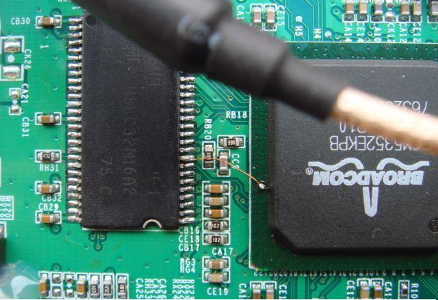
Hi,i need your help!Do you know where the a12 address line is?this picture shows how to connect the a12 line to the ram,but i can't find it!!SOS.
Hey there;
A12 is located on pin 36 of the SD memory chip. So in the picture you provided, the tiny copper wire seems to be connecting A12 to the Broadcom Chipset's A12 lane.
Make sure that your router is using SD Memory [Which is evident from its 27 x 2 pin configuration [54 pins altogether]] otherwise what I said will be incorrect; that Pin 36 is A12
Just out of curiosity, is the picture that you uploaded pertaining to the BCM5352EKPB chipset?
I am interesting about that how do you connect the a12 address leg? I mean which leg or place of cpu connects to the pin 39?Could you show me?
nvram set sdram_init=0x0A
nvram set nvram_ncdl=0
nvram commit
reboot
these commands work for me to enable 16MB RAM.
Hey linuxfree
For all SD-RAM chips, A12 is connected to pin 36. However, for the WRT54G V5, pin 36 on the board is not connected to anything. I unfortunately have not attempted to increase the memory beyond 16MB for my WRT54GV5 using the BCM5352EKPB chipset. However, from the picture which you provided [Under closer inpsection it is in fact for the BCM5352EKPB chipset], in order to enable 32MB of ram, you will first need to make sure that your memory chip is 512Mbit. [check the datashseet for it.]
If it is, you will have to simply solder a wire from pin 36 on the memory chip to the point at which is shown in the picture to the chipset. To reveal the copper track on the chipset, gently use a stanley knife blade and slowly scrape it until you have uncovered it. Once thats done, solder the wire onto the point.
If you were successful, your router should still work; and once you enter in the necessary ram settings to enable 32MB you should now have 32MB of ram for it.
I can not be held responsible for any damage you may cause to your equipment if you try this!