I have not following this thread for a long long
time now. This project of mine still has not
completed. But laterly I have taken some time to get
it done though.
The reason for having 2 antennae for the 802.11g radio
is because one antenna (not sure which one) is meant
for Diversity antenna. This means that it is used for
comparing received signals and see which is better.
If you cut off one of the tracks, then there will be
no diversity antenna and so no comparison. Which leads
to another problem if there are multi path signals
(signals reflected from other objects, your router
won't able to detect which is the correct signal)
Despite all this, if you really want to go ahead
with it then you should solder the signal at one end
of the capacitor that is facing the metamaterial/PCB
antenna. The tiny capacitor which has a lablel: cxxx
supposed to filter out high freq. noise.- I might be
wrong here.
Thanks.
Hi,
Thank you for your reply. I have to try it because the other part of the network is ~300 meters far away from here, so somehow I have to connect my 15 dBi Yagi to this device.
What will happen if I leave the other diversity PCB antenna connected? Probably it won't "see" the AP (which is 300 meters away) only the directinal Yagi. Could it be a problem?:
Thanks a lot!
Cheers,
Oliver
Hi,
For anything that is used for outdooor, it is better to
spend some $$$ and get a proper hardware which is
more reliable than making you own.
This is my opinion. Because I have not set up such
long distance communication before using it as an
AP. Though, I have set up-point-to-point wireless
bridge using 2 Dlink dwl-2100AP. And the distance is
only approx. 60metres
If you have your Yagi connected, and the other
antenna left it untouched, then your Yagi antenna
will have the higher receiver sensitivity to pick
up long distance weak signal, whereas the antenna
will not pick up anything at all.
Regards,
Hi,
I have to use only one device at both sides and I need DD-WRT on the router side at least.
I think you should read this first, before you venture out and
build your own wireless network with dd-wrt. This link
below will give you some ground works about setting
up: AP- AP(wireless repeater).
I think you should read this first, before you venture out and
build your own wireless network with dd-wrt. This link
below will give you some ground works about setting
up: AP- AP(wireless repeater).
This is an update of the my thread on the result
of adding an external antenna on the WNDR3300's PCB.
After many years I started this project, I finally
got my act together and finished the antenna modification.
The MAIN goal of doing the modification is get a
better gain from adding external antenna.
However, to my surprise and sad expectation, after
all the hard work, the result is rather worse off.
What I discovered after the antenna mod:
There is no improvement in signal quality when
external antenna are added. Before adding the ext.
antenna, gain was around about -40 to -45dBm,
however when mod. was done, the gain degraded to -53
to -57dBm.
If external antennae are disconnected/dismantled.
My wireless Netgear WNDA3100 802.11ABGN client
adapter can still managed to associate the router
and getting an IP address from its DHCP server.
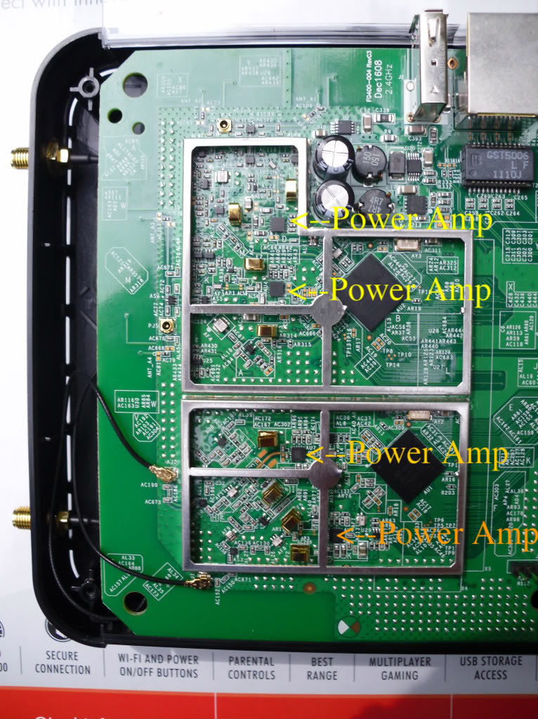
This discovery led me to suspect that the other
passive antennae on the router's PCB (which can be
seen on the picture- left side and right side- close
to the edge of the PCB) is still functioning to
provide signalling wave to and fro my wireless
adapter.
Anyway, I would like to thank those people who help
me get some understanding how the mod was carried
out.
If someone can verify my findings are correct,
then it will be great to sum it up and bring this
thread to a meaningful closing.
This is an update of the my thread on the result
of adding an external antenna on the WNDR3300's PCB.
After many years I started this project, I finally
got my act together and finished the antenna modification.
The MAIN goal of doing the modification is get a
better gain from adding external antenna.
However, to my surprise and sad expectation, after
all the hard work, the result is rather worse off.
What I discovered after the antenna mod:
There is no improvement in signal quality when
external antenna are added. Before adding the ext.
antenna, gain was around about -40 to -45dBm,
however when mod. was done, the gain degraded to -53
to -57dBm.
If external antennae are disconnected/dismantled.
My wireless Netgear WNDA3100 802.11ABGN client
adapter can still managed to associate the router
and getting an IP address from its DHCP server.
This discovery led me to suspect that the other
passive antennae on the router's PCB (which can be
seen on the picture- left side and right side- close
to the edge of the PCB) is still functioning to
provide signalling wave to and fro my wireless
adapter.
Anyway, I would like to thank those people who help
me get some understanding how the mod was carried
out.
If someone can verify my findings are correct,
then it will be great to sum it up and bring this
thread to a meaningful closing.
Thanks!
Hi,
I've been using this mod for more than one year. I connected to WNDR3300 in bridge mode. I use two 15 dB Yagi antennas and there are ~300 meters between the two routers.
It is good hear you have successfully modified your
WNDR3300 routers to peform a bridge in a outdoor
environment .
Q1) What kind of Bandwidth you are
getting using "iperf" at a distance of 300m on your
WNNDR3300 wireless bridge?
Q2) Are you using DD-WRT firmware on your wireless
bridge?
Q3) Are you using 802.11 g or 802.11 n on wireless
bridge?
But in my case, my antenna modification is for usage in
an indoor environment. Gain that I measured using
Wireless Mon v4 software was showing no improvement.
I would expect the gain (in terms of dBm) will
increase ( e.g. -40 increase to -30)
due to better gain of ext. antenna.
I am no RF engineer, but I suspect the WNDR3300
router's whole section of PCB is like a huge
antenna itself. So, if ext. antenna (indoor antenna)
like black omni-directional with 90 degree tilting
joint is used for antenna modification purpose,
the signal will get affected.
However, in your case if you have your router
sitting in your house somewhere, and have RF cable
joining from your router to the outdoor yagi
antenna.
The signal emitting out will not get affected by the
router PCB antenna that much since there is a
separation between the both.
But this is only a thoery of mine not a fact unless
I can prove it.
Q1) I haven't used that app but I could try it if you can guide me
Hi,
Sure, not a problem. I assuming you know about
Windows XP. (Sorry, I don't know about other OSes)
First, you must 2 PCs or 2 laptops or combination of
1 laptop and 1 PC for the purpose of testing.
Next, find out what the network IP address.
It should be something like, 192.168.???.???
Assuming you have a PC connected to a router at
home, let that PC be your server. Take note
the PC network IP address = 192.168.???.??? of
your PC going be the server.(You going use this
numbers later at this tutorial, see below)
Write it down on a piece of rough paper.
To find out you PC or laptop's IP address.
Go to Command Prompt,that click on the "Start"
in Windows XP, go to "Programs" and then go to
"Accessories", you will find "Comand Prompt"
there, click on the icon, then type:
ipconfig /all
Now, it is time to pick which is going to be your
server and which is going your client.
Assuming you have a laptop connected to a router on
the other side of the point-to-point link, that
let the laptop be your client.
Next, disable all software firewalls / built in
Windows firewall for your PC and laptop machines.
Search in google and download a small file called:
iperf.exe
Once you have found it, download it and save into a
folder, name it "iperf" in C drive for both PC and
laptop.
On your server PC, run "Command Prompt" again.
Type the following commands follow by pressing
ENTER key for each line of commands:
-----------------------------------------------------
cd \
cd \iperf
iperf -s
-----------------------------------------------------
(this means run the iperf on a PC as a server, listen
to TCP port =5001)
On your client laptop, run "Command Prompt" yet again.
Type the following commands follow by pressing
ENTER key for each line of commands:
-----------------------------------------------
cd \
cd \iperf
iperf -c 192.168.???.??? -t 100000 -i 5
-----------------------------------------------
(this means run the iperf on the laptop as a client
connecting to a server IP address, for 10,000 second
showing Bandwidth result every 5 seconds interval)
If everything is done correctly you should see a list
of Bandwidth values continuously displaying on the
Command Prompt window till the time 10,000 seconds
has reached. Something like, 20Mbps, 25Mbps, etc.
Q2) Are you using DD-WRT firmware on your wireless
bridge?
The reason that I ask this question is because, I
have gathered infromation somewhere that using
DD-WRT firmware or any 3rd party firmware is not
going to give you MORE performance in terms of
raido signal speed/throughput. Partly because
developers are not using the original linux drivers
for the radio chipsets. I might be wrong but you
can check out in the DD-WRT firmware.
I would say that having stock firmware will give
you better speed than DD-WRT firmware, however, the
features are not as plentiful with the stock firmware.
Anyway I've just started a project the replace the devices to WNDR3700v2.Very Happy
I have seen this router PCB, it has U.FL connectors
for the 5GHz radio, which is to me is highly
recommended to those who looking for modifying and
installing a better gain of antenna.
I don't recommend hacking the 2.4GHz radio to have ext
antenna, because if you do, the benefit is a lot
worse than before doing the modification.
Unfortunately my friend (who is on the other side of the bridge) has been out of town for 2 weeks, so I still haven't had a chance to try it.
Anyway I've tried it on my laptop and it gave me strange results. While I can easily copy with 11-12 MB/sec between the laptop and the desktop machine until then I only got ~30 Mbits/sec in iperf.
I've chosen DD-WRT because of the plenty of features. Performance is not everything for me.
We've already hacked the 2.4GHz radio. We changed the two hiroshi connectors to U.FLs and it works. You can see some pictures about a very similar mod here at the end of the page.
Anyway I've tried it on my laptop and it gave me strange results. While I can easily copy with 11-12 MB/sec between the laptop and the desktop machine until then I only got ~30 Mbits/sec in ip
Hmmmmm.......... very strange, how did you get the
figures:- 11-12 MB/sec, that translates to 88-96Mb/sec.
I am still puzzled,
It has to be some error here, because, for speed
of 802.11g, it should around 11-12 mbps. It is
always have half of 54Mbps.
Did install a netmeter software to the speed of the
copying the files?
We've already hacked the 2.4GHz radio. Twisted Evil We changed the two hiroshi connectors to U.FLs and it works. Laughing You can see some pictures about a very similar mod here at the end of the page.
Of course, it will work, but in reality is if you do
any modification, you must take a measurements in
of gain/speed/bandwidth BEFORE and AFTER modification,
to see if there is any improvement. To me if you get
slow speed after the modification, then it will be a
waste of time and money to the same modification on
another new router.