Joined: 31 Mar 2007 Posts: 181 Location: /Earth/USA/OH/Zville
Posted: Sun Dec 07, 2008 14:13 Post subject:
Unfortunately I do not have the flash that you are looking for. Figured I'd say that so this gets bumped to the first page again.
I would think that it is a good idea to start collecting these for in case people do use the wrong vxworks_killer on there router and have a need to go back to stock. _________________ WRT-350N v1.0; 128MB RAM, WPC600N, Dual USB, Mini+USB+FTP NEWD, CPU@330Mhz, Terk WF-R x3, Serial, external jtag, and working on SD Mod. Running Samba3, Lighttpd, and some Python apps.
WRT-300N v1.1; 128MB Ram, USB1.1, Bricked
I figured out somewhat of what the problems was. For some reason when I flashed the CFE back to the router It was not asking for tftp at boot. I was able to get to the CFE prompt and use the flash command thier to tell the router to flash dd-wrt.v24_micro_generic from a local tftp server like so:
flash -noheader tftp server IP:dd-wrt.v24_micro_generic.bin flash0.os
Or in my case since my windows pc with IP of 192.168.2.10 is running a tftp server with dd-wrt.v24_micro_generic.bin in it's root folder and with router configured as 192.168.2.50:
So I dumped wholeflash using tjtag and with Tornado's help found that the CFE was writing the firmware 28 bytes off from where it should be writing the firmware.
************************************************************
UPDATE: found that if I use this it works perfectly to flash firmware:
have to leave the .os off the end otherwise it still flashes at the same spot (28 bytes off from where it should flash) and ignores the offset switch.
*************************************************************
Should be writing firmware at 0x1c040000 or offset 262144 and was starting the write at 0x1c04001c or offset 262172 and therefore CFE was looking for boot block at 0x1c040000 or offset 262144 and not finding it resulting in a "Invalid boot block on disk". Still not sure why the CFE was doing this.
I had to rename dd-wrt.v24_micro_generic.bin to kernel.bin and flash it with tjtag as a kernel. tjtag starts writing the kernel at 0x1c040000 (offset 262144) so this put the firmware at the right starting address on the flash and when I rebooted It started looking for tftp and failed then successfully found a boot block on Flash0 and router is up and running with Micro_Generic.
I went ahead and logged into web interface and upgraded it to MEGA, and it took.
Thankyou Tornado. I appreciated the help with this.
dd-wrt_status.PNG
Description:
Filesize:
57.9 KB
Viewed:
15413 Time(s)
_________________ Linksys - WRT54GS Ver 7.2 (usb port added)
Belkin - (PLAY) F7D4302 Ver 1
Asus - WL500G Premium Ver 1
Asus - RT-N16
Last edited by eddie97044 on Thu Dec 11, 2008 15:26; edited 9 times in total
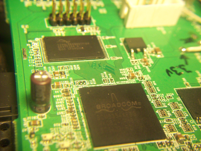
You see in this PIC the jumpers I had to add at R5 and R7. I also replaced R2 but this is not necessary as it is already a 0 ohm smd resistor factory installed.
Oh and if you think that jumper looks funky at R7, that is because I accidently burnt the pad off the board, but R3 and R7 pads closest to the flash chip are conneted on that side by a trace so I just jumpered diagonally from R7 pad on one side to R3 pad on the other. Same difference as if you just jumpered R7 location.
100_0004.png
Description:
Filesize:
667.62 KB
Viewed:
15401 Time(s)
_________________ Linksys - WRT54GS Ver 7.2 (usb port added)
Belkin - (PLAY) F7D4302 Ver 1
Asus - WL500G Premium Ver 1
Asus - RT-N16
Also antennas are removed in this pic as they where getting in the way of things. I will put them back on later when I am done replacing ram chip next.
100_0012.png
Description:
Filesize:
720.84 KB
Viewed:
15398 Time(s)
_________________ Linksys - WRT54GS Ver 7.2 (usb port added)
Belkin - (PLAY) F7D4302 Ver 1
Asus - WL500G Premium Ver 1
Asus - RT-N16
Joined: 30 Nov 2008 Posts: 206 Location: Wherever the wind blows.
Posted: Thu Dec 11, 2008 0:37 Post subject:
Excellent work Sir !
I would be interested in your soldering techniques for sm devices (Removing and refitting). I have done some small stuff, and one 28 pin device. Are you using standard soldering gear or special smt adapters for the iron ?.
Joined: 31 Mar 2007 Posts: 181 Location: /Earth/USA/OH/Zville
Posted: Thu Dec 11, 2008 7:49 Post subject:
Bravo! I just wish my ram upgrade for my 350N went as well as yours. Waiting for a jtag cable to find out it get a flashing power light.... _________________ WRT-350N v1.0; 128MB RAM, WPC600N, Dual USB, Mini+USB+FTP NEWD, CPU@330Mhz, Terk WF-R x3, Serial, external jtag, and working on SD Mod. Running Samba3, Lighttpd, and some Python apps.
WRT-300N v1.1; 128MB Ram, USB1.1, Bricked
I would be interested in your soldering techniques for sm devices (Removing and refitting). I have done some small stuff, and one 28 pin device. Are you using standard soldering gear or special smt adapters for the iron ?.
Rudds
Tools needed:
-Small flat head screw driver or even a dental pick would work. Just something to use to get under the flash chip for leverage.
-15 Watt soldering iron from radio shack (Part# 64-2051B)
-Desoldering Braid from radio shack (Part# 64-2090E)
-Isopropanol or other cleaning agent to remove old soldering flux.
-Q-tips for the Isopropanol (Just thought I would add this for clarity)
-Magnifying glass to inspect for connected pins when done soldering.
Removal of flash old chip:
Actually the desoldering of the flash chip was easy. First make sure you take note of the orientation of the original flash chip. Pin 1 specifically so as when you install the new chip it goes the same way. I just took a small flat head screwdriver like from an eye glass repair kit and put it under one side of the flash chip. I then proceeded to run a beed of solder all the way accross all the pins on one side of the flash chip and slowly popped that end of the chip away from the board while heating the bead to loosen that side, then repeat the process while holding the chip and just removed it from the board. Cleaned the contacts by using desoldering braid witch can be purchased at your local radio shack (Part number 64-2090E). Place the desoldering braid on the contacts and heat the braid with your iron to soak up the left over solder that is stuck to the contacts. Then make sure you clean the area up with Isopropanol. Cleans all the flux from the area.
Install of new flash chip:
After making sure all the old solder is removed from the contacts on the board using the desoldering braid and cleaned with isopropanol. Place new chip and line up it's pins with the contacts on the board. Make sure the alignment is correct before tacking chip to board (Pin 1 is where pin 1 should be). I then tacked the chip to the board on one corner with solder. Don't worry if you connect pins with solder at this point. Tacked the rest of the corners. Then just ran a bead of solder all the way a crossed all the pins on both sides. Then took the desoldering braid and laid it on the pins and heated it up with the iron which soaked up all the excess solder and pulled all the solder out from between the pins and made it look quite professional if I say so myself. Might want to clean the area with Isopropanol again just to remove any left over resin flux. Solder flux can be corrosive over time. Then inspect with the magnifying glass to make sure that none of the pins on the flash chip are bridged with solder and also that they are securely bonded to the board.
Note:
This was actually way easier than I thought, of course I have had a lot of soldering experience so I don't know if I would try it otherwise. And I wasn't to worried about the heat on the new chip as when it arrived it was in a static bag that says "NOTICE Parts are moisture sensitive. Bake prior to vapor or IR soldering to reduce the chance for damage. I just thought that was funny. They want me to bake the flash chip in an oven if I was using these methods. _________________ Linksys - WRT54GS Ver 7.2 (usb port added)
Belkin - (PLAY) F7D4302 Ver 1
Asus - WL500G Premium Ver 1
Asus - RT-N16
Joined: 30 Nov 2008 Posts: 206 Location: Wherever the wind blows.
Posted: Thu Dec 11, 2008 19:41 Post subject:
Eddie, super stuff, never thought of running a bead and cleaning it up with solder braid after !
Nice one.
Could you now please post a walkthrough for the jtag tools, with everuthing you have learnt, on how you you do it next time ?
That would be very useful.