I can connect to WNDR3300 using 5GHz at speed 270 MBps. But actual transfer speed is much slower - I'm getting around 5 MBytes per second. Connect on 54 MBps gives below 3 MBytes per second. I couldn't find any significant difference between 135 and 270 MBps.
I didn't try latest Eco build yet (11536), but others reported better performance.
I guess there is no harm of drill holes on the side
or the router to fit in the bulkheads.
Not sure whether it is possible to fit the heads on
top of the router. I think the bottom of the head will
be touch the PCB or even the IC chips. So I guess the
best is to try it on the side instead of at the top.
Soldering a pigtail (COAX) is a good way to do but you need to have the braid almost up to the edge of the place you cut the center conductor. Otherwise it acts like the antenna. Also the coax has to be good for this frequency range and at 5ghZ for example you might be only able to get away with semi hard coax.
There is an option in DD-WRT to select left / right antenna btw from my limited playing around with this.
Adding those little whip antennas (I think) does very little to expand the range. Google the Cantenna and use 4" type can (And if you have a soldering gun) solder a second can to get a more proper antenna. Its FAR FAR better for those point to point connections. The next step up is to use an old TV Disk.
The DD-WRT firmware lets you adjust up the power output but I've heard a few folks say it can overheat the unit. *Mine runs hot at stock speed. So adding a small fan might be in order.
GREAT Thread and thanks to whoever is posting this information.
Has anyone been able to find application notes and programming information on the Broadcom parts? I would like to see the logic behind these multi antennas and see for example which is Left and which is Right on the WL1 "Radio"
I suppose I can solder a pigtail to on and run it to my 2.4ghz Cantenna and just observe what it is but... I would like to know whats really going on.
Are they trying to make these antennas directional with these extra slots? As far as I can tell they might make the router a tiny bit "directional" but the claims that this is 7 antennas is (I think) rather bogus. Its too bad they don't understand that there are times we need to plug in a directional antenna to get our wireless to where it needs to go. By the way I tried Repeater mode with this and it seems to work great so far.
Thanks and BRAVO to the dd-wrt authors!
I tried to repeat both my 802.11g AND 802.11a signals from the basement and seemed to have some problems. But the simple repeater of mode g works flawlessly. *This is almost for sure "operator error" on my part.
I'm finishing my second 2.4 Ghz N connector Cantenna. It looks nice & I wonder what people do for setting them up full time in one location? I just made a "U" of three small pieces of 2x4 and taped the mess together. I put some strips of double sided tape after aiming it at my local WiFi hotspot.
BTW anyone have any good design info on a 5 Ghz Mode A antenna? The "can" size is rather small but I suppose a little larger won't hurt it.
Joined: 31 Aug 2009 Posts: 2448 Location: Third Rock from the Sun
Posted: Mon Jun 14, 2010 5:18 Post subject:
twinmos wrote:
About dual band antennas and connectors - I bought it from Digikey. (digikey.ca).
Dual band Antenna - Part number 553-1313-ND
U.FL connector - Part number H9161-ND
Sorry for the nekro
I had a look through digakey and cannot seem to find what I am looking for. Do you know if they offer a pigtail assembly with the U.FL connector on one end and the antenna connector on the other end? Thanks. _________________ Peacock Thread-FAQ -- dd-wrt Wiki
Joined: 26 Jan 2008 Posts: 13049 Location: Behind The Reset Button
Posted: Mon Jun 14, 2010 12:59 Post subject:
Dark_Shadow wrote:
twinmos wrote:
About dual band antennas and connectors - I bought it from Digikey. (digikey.ca).
Dual band Antenna - Part number 553-1313-ND
U.FL connector - Part number H9161-ND
Sorry for the nekro
I had a look through digakey and cannot seem to find what I am looking for. Do you know if they offer a pigtail assembly with the U.FL connector on one end and the antenna connector on the other end? Thanks.
Joined: 31 Aug 2009 Posts: 2448 Location: Third Rock from the Sun
Posted: Mon Jun 14, 2010 16:28 Post subject:
The link for the dual band antenna says R-SMA. What type of connector is that or is it just short for RP-SMA? _________________ Peacock Thread-FAQ -- dd-wrt Wiki
Joined: 10 May 2008 Posts: 1380 Location: Pacific North West, USA
Posted: Mon Jun 14, 2010 17:32 Post subject:
Dark_Shadow
Please post if those UFL -> RPSMA adapters work for the WNDR3300!
Always wanted to add externals, but my soldering skills suck.
If you can just add some cables - I may mod my pair of WNDR3300's as well. _________________ Soylent Green Is People ! =-=-=-=-=-=-=-=-=-=-=
Netgear Nighthawk R7000 - DD-WRT Build R46220
Linksys EA8500 - OpenWRT IPQ806x Trunk R16375 5.4 Kernel
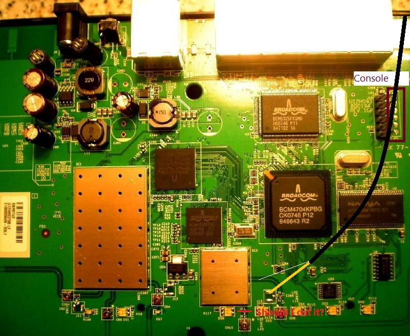
I just wanted to update this thread with some new info:
Marked in purple is the "right" wl1 antenna in dd-wrt.
Hi,
I'm going to add an external RPSMA connector to WL1 side because I want to connect a directional Yagi antenna to it. So if I understand this whole thread correctly then I only have to solder a wired RPSMA connector to the purple coloured wire. Should I cut the source of the "receiver only" smart/pcb antenna part of the WL1 to avoid interference?
I have not following this thread for a long long
time now. This project of mine still has not
completed. But laterly I have taken some time to get
it done though.
The reason for having 2 antennae for the 802.11g radio
is because one antenna (not sure which one) is meant
for Diversity antenna. This means that it is used for
comparing received signals and see which is better.
If you cut off one of the tracks, then there will be
no diversity antenna and so no comparison. Which leads
to another problem if there are multi path signals
(signals reflected from other objects, your router
won't able to detect which is the correct signal)
Despite all this, if you really want to go ahead
with it then you should solder the signal at one end
of the capacitor that is facing the metamaterial/PCB
antenna. The tiny capacitor which has a lablel: cxxx
supposed to filter out high freq. noise.- I might be
wrong here.