#1
slide off the Left side gray cover by pushing it to the back.
#2
under this you will find a sticker under this sticker you will find a screw : Remove this screw.
#3
on the bottom cut the sticker along the center front to back.
#4
were you see WAN on the back is a "lock" pry open the router from the Back.
just slowly work at it from here you will get it.
_________________ You can find me Here:
http://www.facebook.com/#!/profile.php?id=100001843308666
Ok.. read through this whole thread and some others, I've got the squiggly line in inSSIDer for my router but not for any others around me. I'll post a screen shot. Changed my 12v 1A plug to a 12v 4.54amp plug I had around. Also set the "wl txpwr1 31" and not quite ready to dismantle my router, any thing else I can check before going the next step?
The other router shown is in the house next to me being broadcast through a cement wall and probably 100ft away and who knows where in their house. Not a strong signal but a stable one! Mine shown as dd-wrt is up and down at any distance.
This shuld help "some"
it looks like the antenna diversity is kicking your butt.
try this set your TX Antenna to Right
and RX Antenna to left.
or
TX Antenna and RX Antenna to right.
Beacon Interval 50
thats all i can help ya with on a "stock" router.
I hope it helps.
8)
PS.
Its Hard to get it Perfect it takes Work :D
AND KEEP the router AWAY from power cords , power transformers.......
well away from ALL other Electronic devices. Even the House Wiring in the wall can mess with ya. _________________ You can find me Here:
http://www.facebook.com/#!/profile.php?id=100001843308666
Joined: 09 Jul 2006 Posts: 71 Location: Nanaimo BC Canada
Posted: Tue Aug 04, 2009 6:47 Post subject:
Radioman193 wrote:
This shuld help "some"
it looks like the antenna diversity is kicking your butt.
try this set your TX Antenna to Right
and RX Antenna to left.
or
TX Antenna and RX Antenna to right.
Beacon Interval 50
thats all i can help ya with on a "stock" router.
I hope it helps.
8)
PS.
Its Hard to get it Perfect it takes Work :D
AND KEEP the router AWAY from power cords , power transformers.......
well away from ALL other Electronic devices. Even the House Wiring in the wall can mess with ya.
Haaa....
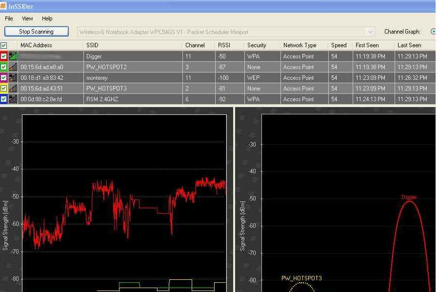
Check this out...Did what you said Radioman. 11:20-11:21 is my original setup with power cords jumboled all over each other...11:22-11:23 is TX and beacon changes...11:28 is power cord move away from others and in a seperate wall plug with no extension cord...hmmmmm...guess I cropped out the times but you get the picture.
Thanx for the "howtocrackopenabuffalo" also.
squibt
HP54G-3.JPG
Description:
Filesize:
51.28 KB
Viewed:
13447 Time(s)
_________________ Buffalo WHR HP 54G
Linksys WRT 54 GS V1
Linksys WRT 54 G V2
2Wire (dont ask)
Joined: 09 Jul 2006 Posts: 71 Location: Nanaimo BC Canada
Posted: Tue Aug 04, 2009 16:01 Post subject:
Radioman193 wrote:
The Mods are Complete and have passed all my tests.
and i replaced the 5volt 1.4amp power supply with a 5volt 2.5amp .
Cisco Systems power supply
Part # 34-0912-01 REV:A0
Now
the first thing we have is the Power mod.
we need to remove the board from the router
after this we look on the back side of the board up to the front you will find IC1 the regulator for the Rf amp that is set to run on +4.52 volts we want +5.04 volts the picture will show you what to do.
And for the people that think thave a bad Buffalo WHR-HP-G54 if it has Verry low power CHECK the fuse.
same for the people that think thay burnt there amp up CHECK YOUR fuse!
Its in the picture.
AFTER you put it back together
in your Browser go to
#1 192.168.1.1
#2 Login
#3 click on the Administration tab
#4 then click the Commands tab
#5 then in the Command Shell Box
#6 Enter this >> wl txpwr1 31
#7 then click Save Startup "you need to do this step cause if or when you reboot the router it will come back up with only 251mW'
#8 then at the top click the Management tab
#9 then At the bottom Click the Reboot Router Tab
after it reboots repete steps 1 and 2
then click on the Status tab at the top
then click the Wireless tab
you shuld see TX Power 1259 mW
close your browser
Enjoy the "toy"
Radioman...
What is the C11 chip on the flip side of the fuse? Will it fall off when the fuse is removed? I think I'm gonna take the router into an electronics shop and have them do the soldering...sooooo smallll can't see em...
squibt _________________ Buffalo WHR HP 54G
Linksys WRT 54 GS V1
Linksys WRT 54 G V2
2Wire (dont ask)
The Mods are Complete and have passed all my tests.
and i replaced the 5volt 1.4amp power supply with a 5volt 2.5amp .
Cisco Systems power supply
Part # 34-0912-01 REV:A0
Now
the first thing we have is the Power mod.
we need to remove the board from the router
after this we look on the back side of the board up to the front you will find IC1 the regulator for the Rf amp that is set to run on +4.52 volts we want +5.04 volts the picture will show you what to do.
And for the people that think thave a bad Buffalo WHR-HP-G54 if it has Verry low power CHECK the fuse.
same for the people that think thay burnt there amp up CHECK YOUR fuse!
Its in the picture.
AFTER you put it back together
in your Browser go to
#1 192.168.1.1
#2 Login
#3 click on the Administration tab
#4 then click the Commands tab
#5 then in the Command Shell Box
#6 Enter this >> wl txpwr1 31
#7 then click Save Startup "you need to do this step cause if or when you reboot the router it will come back up with only 251mW'
#8 then at the top click the Management tab
#9 then At the bottom Click the Reboot Router Tab
after it reboots repete steps 1 and 2
then click on the Status tab at the top
then click the Wireless tab
you shuld see TX Power 1259 mW
close your browser
Enjoy the "toy"
Radioman...
What is the C11 chip on the flip side of the fuse? Will it fall off when the fuse is removed? I think I'm gonna take the router into an electronics shop and have them do the soldering...sooooo smallll can't see em...
squibt
lol
no it will not
_________________ You can find me Here:
http://www.facebook.com/#!/profile.php?id=100001843308666
Hey, Radioman ... what happens if in the Wireless/Advanced Settings tab i set both, RX and TX antennas to "Left" or "Right" ?
In this case if i want to upgrade the antenna(s) i'd need only one? (WRT54GL)
Thanks in advance!
Quick question, how did you manage to get the power up on the 300N with the glich that prevents us from properly adjusting the power levels? I just picked up a 350N that I'm going to make my "range" ap, but that sortware issue is holding me up.
Hey, Radioman ... what happens if in the Wireless/Advanced Settings tab i set both, RX and TX antennas to "Left" or "Right" ?
In this case if i want to upgrade the antenna(s) i'd need only one? (WRT54GL)
Thanks in advance!
Still having unstable trasmit power according to inssider. Had my stock 5v 2.6 amp buffalo brick. Upgraded to a 5v 4 amp, doesnt fluctuate as much but not a flat line at all. Thinking about getting a 6v adaptor with a high amp rating and using a Potentiometer to adjust the voltage down to around 5.4 5.5 then jumpering the amp off the dc jack instead of the 5.04 off ic1. Anybody have any suggestions? Im also woried slightly that i might burn my amp if the brick fluctuates at all, should i fuse it or overkill? Will the rest of the board run ok at 5.5v? Awesome thread by the way, took me a while to get everything working, thinking geting a 15db antenna to go with it lol.
FYI, Going between 251mw and 1259mw I get aprox 6% increase in signal strength to my all my phones, laptops, etc. Going by the signal meter in wireless settings, very quick assesment. _________________ WHR-HP-G54
Power Mod
7db Rubber Duck Antenna
DONT do 6V !!!!!!!!
and
DONT jump power from the power jack to the rf amp!
if you do and fry it dont say it was my fault.
Im not saying it will not work thats just pushing your luck for a device that is on 24/7.
and you might not get a completely flat line .
But the flater the better even mine dont stay flat it only is about 80% of the time .
and took alot of work to get it that way.
_________________ You can find me Here:
http://www.facebook.com/#!/profile.php?id=100001843308666
Any specific details on these hacks? From your first few post you only mentioned things like power supply modification (caps on the card, bigger input PSU, PSU caps) and shielding. Those of course would decrease noise and increase stability, but not increase the gain of the amplifier stage or the input sensitivity.
And additional details (preferably as technical as possible, EE in training), would be appreciated.